D-Flip-Flop
The beginning of the DSD course is mainly concerned with combinatorial circuits, whose outputs are entirely determined by the inputs. These circuits are also said to contain no memory action.
The sequential circuits will gradually become more and more important in the course, and the D-Flip-Flop is the major player in this change.
This tutorial is not intended to replaced the course on D-Flip-Flop, but to enable you to put into practice what has been taught in Logisim.
Adding a D-Flip-Flop to your circuit
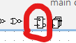
A D-Flip-Flop is an important component, so it belongs in the toolbar, where you can add it from.
What to connect to a DFF and how?
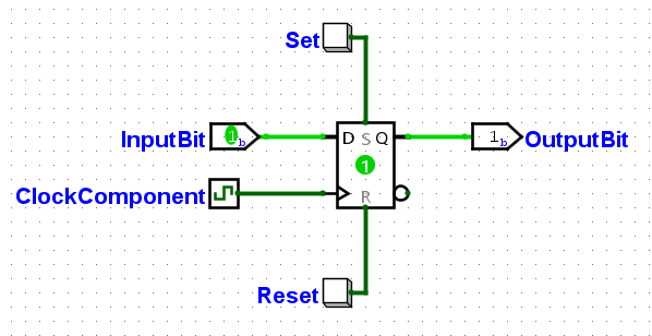
A D-Flip-Flop (DFF) is used to store one bit.
NOTE
The DFF is only the component in the middle, the others are simply connected to it.
WARNING
The names used are not mandatory to be these ones and can be changed depending on the situation and the TP.
When the ClockComponent signal changes from 0 to 1, the InputBit input value replaces the OutputBit value.
Set and Reset, on the other hand, are asynchronous, i.e. they don't wait for the clock to change from 0 to 1 before changing the DFF value.
Set force the DFF value to become 1 as soon as it is set. Reset forces the DFF value to become 0 as soon as it is set.
The behavior when Set and Reset are activated at the same time depends on the DFF. The Logisim project used in this tutorial is available in the appendix. It allows you to play with the DFF and see how it behaves.
TIP
Clocks are covered in another tutorial.
Using Set/Reset
The tutorials did not cover the form of input used for Set and Reset above. They are simply two buttons. They produce a 1 signal when clicked, 0 the rest of the time.
In the graded labs, when a circuit is said to need an asynchronous reset, this will mean using one of these DFF inputs (not necessarily with buttons though).
In general, the TP instructions provide a default value to be set when the circuit is reset. From here we :
- Define what values the DFFs must contain to be in the described state at reset (
1or0for each DFF) - Use either
SetorResetinput on each of the DFFs depending on whether it should contain1or0at reset.
Whether you choose Set or Reset, the signal will be linked to a reset button or something similar. This is because the circuit does not know when it started, and only a general reset can put the circuit in the desired state.
CAUTION
If the instructions ask you to implement a synchronous reset, the Set and Reset inputs of the DFF must not be used, as they are asynchronous by definition. Instead, reset logic should be applied to the InputBit input.
Appendix
TIP
To familiarize yourself with DFFs, what better way than to download the project used in this tutorial, click around and see what happens?
The clock can be activated manually, or it can be activated regularly and automatically as explained in this tutorial.
The Logisim project used in this tutorial can be downloaded from this link.