Mastering sub-circuits (Logisim)
The circuits to be implemented become increasingly complex, to the point at which doing everything in a single main circuit is no longer the most viable option, in graded TPs for example.
As in programming, the idea will be to modularise and extract repeating parts from the circuit. In programming, there are functions. In Logisim, there are sub-circuits.
Main circuit and sub-circuits
Logisim allows you to create several circuits rather than a single one, in order to modularize the required functionalities.
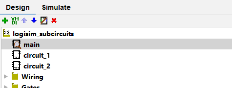
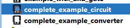
The list of circuits is displayed in the same place as the additional components :
TIP
In the image above, the main circuit has a magnifying glass icon next to it. This means that main is the circuit currently displayed in the working area.
To open another circuit, it is necessary to double-click on it.
Creating new circuits
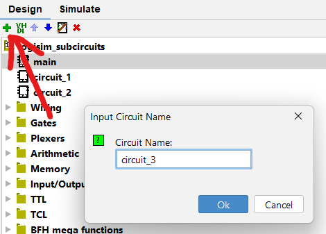
A new circuit can be created using the green button with an plus icon :
How a sub-circuit works
Circuits created in Logisim generally have inputs and outputs (a circuit without them is of little interest).
The user can then use his own circuits in other, more complex circuits, by giving them the necessary inputs.
Examples are probably much more telling.
Example 1 : Custom AND gate
Let's suppose we have an and_gate circuit whose only function is to apply an AND gate to its two inputs.
This is not a very useful circuit, but it's simple enough for a first example.
We want to use this and_gate circuit instead of a simple AND gate. To do this, follow these steps :
- Open the circuit where you want to add an
ANDgate if it is not currently open. - Select the
and_gatecircuit with a single click (not a double click) :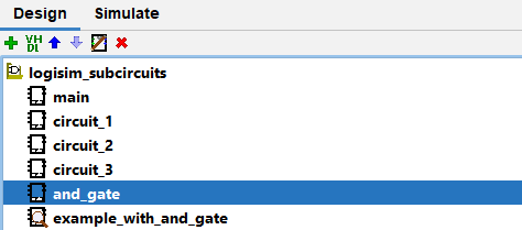
- Add the
and_gatecomponent as a normal component, by clicking in the work plan. - Connect the added component with the desired inputs and outputs.
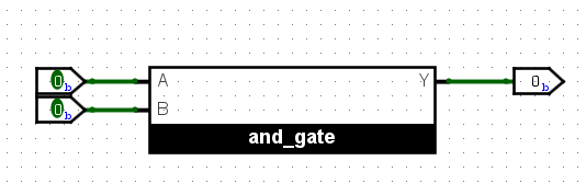
This implementation provides two inputs to and_gate and retrieves its output.
IMPORTANT
It is not obligatory to give Input components as input or to recover the output of the sub-circuit with an Output component. It is perfectly possible to apply logic to the inputs and outputs of a sub-circuit, for example using the output in a DFF instead of an output directly.
NOTE
By default, sub-circuits are displayed as large rectangles as shown above. It is possible to change this appearance in the sub-circuit's properties, by editing Appearance, and right-clicking on it to access Change Appearance which will open a circuit appearance editor.
This is purely aesthetic and completely useless in terms of a potential grade, it is not advisable to spend any time on it, unless you want to have some fun.
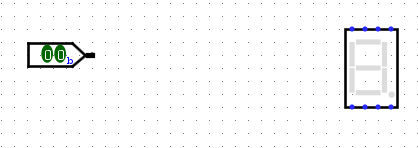
Example 2 : 7-Segment Converter
Given a 2-bit input, we want to display the decimal value it represents on a 7-Segment Display.
One possibility would be to perform the conversion in this circuit directly, however :
- This circuit would be less readable
- Other conversions might be required elsewhere
Creating a sub-circuit therefore seems the appropriate choice.
Let's create a circuit that takes a 2-bit vector as input and outputs an 8-bit vector representing the 8 bits to be given as input to the 7-segment display.
Moreover, we can simply generate the conversion circuit from a truth table.
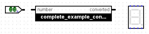
If we name the main circuit complete_example_circuit and the converter complete_example_converter, we end up with the following display :
So we add the conversion circuit to the main circuit :
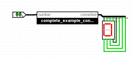
Then, using a Splitter, we can separate the converter's output bits and give them as input to the 7-Segment Display.
NOTE
We could also have chosen to have 8 output bits from the sub-circuit rather than a single vector of 8 bits.
Appendix
The Logisim project used in this tutorial can be downloaded from this link.
The truth table used to generate the converter can be downloaded from this link.