Splitter (Logisim)
As already discussed in a previous-tutorial, individual bits won't be enough for the whole semester, and there will come a time when inputs will look more like this :

You may wish to perform an operation with specific bits of this vector rather than the whole vector. This is a regular occurrence, which is why the Splitter is so important.
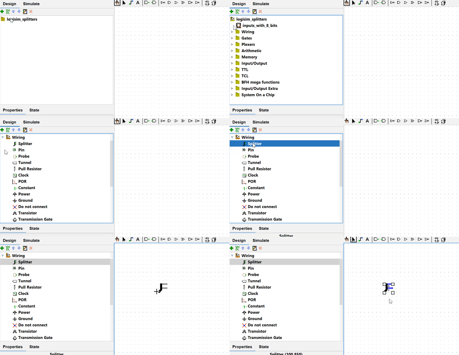
Add a Splitter to your circuit
The Splitter is an additional component found in the component hierarchy seen earlier in the folder called Wiring and under the name Splitter.
To add it to a circuit, click on it to select it and click in the circuit where it should be added.

Using and adjusting the Splitter
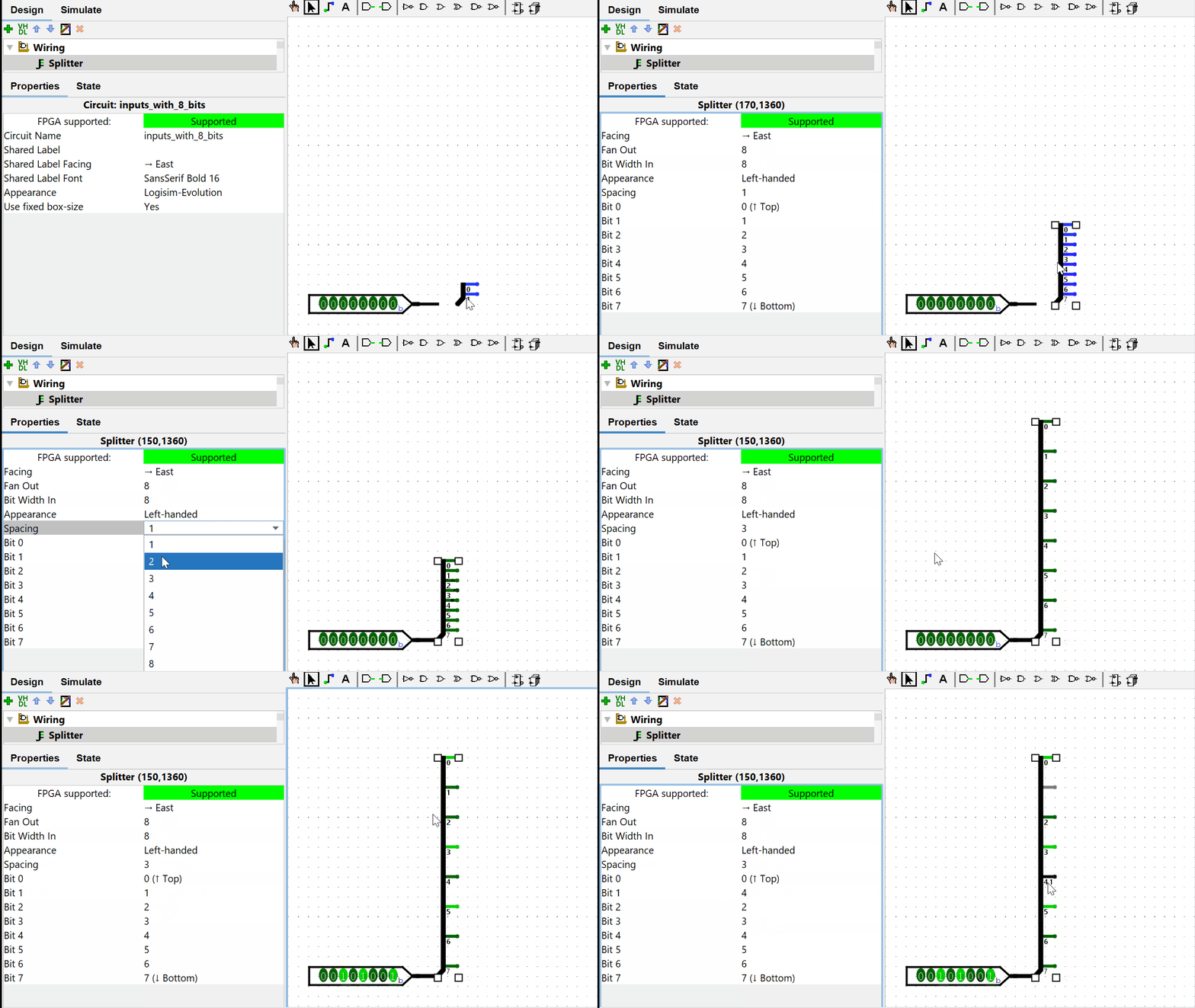
By default, the Splitter is not yet configured to our liking :

The following properties can be used to set up the Splitter as required :
| Name | Description |
|---|---|
Fan Out | Number of wires outputting from the Splitter |
Bit Width In | Number of bits taken as input to the Splitter |
Bit i | Indicates which output wire the i-th input bit will go into |
Spacing | The number of points separating each output thread |

TIP
The best way to master Splitters is to experiment with their properties.
Take several bits and combine them into a vector
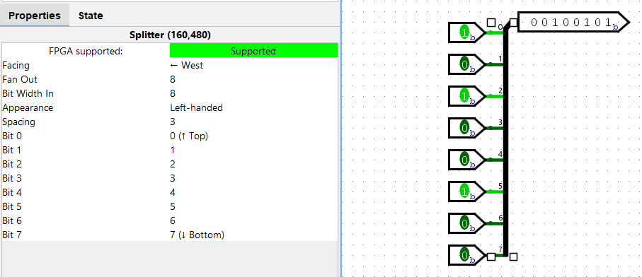
The Splitter can be used to select specific bits within a vector of bits. It can also be used to perform the opposite operation and assemble bits into a vector.
To do so, simply connect the individual bits to the wires described so far as 'outgoing' from the Splitter. The only thing that changes is the direction.
To make this more visual, one can also change the appearance of the Splitter in its properties so that it is rotated.

Appendix
The Logisim project used to illustrate this tutorial can be downloaded from this link.