General Logisim UI
The following tutorials are designed to help you get the most out of Logisim.
The aim of this tutorial is to help you get to know Logisim's interface. The UI is broken down into 5 main parts :
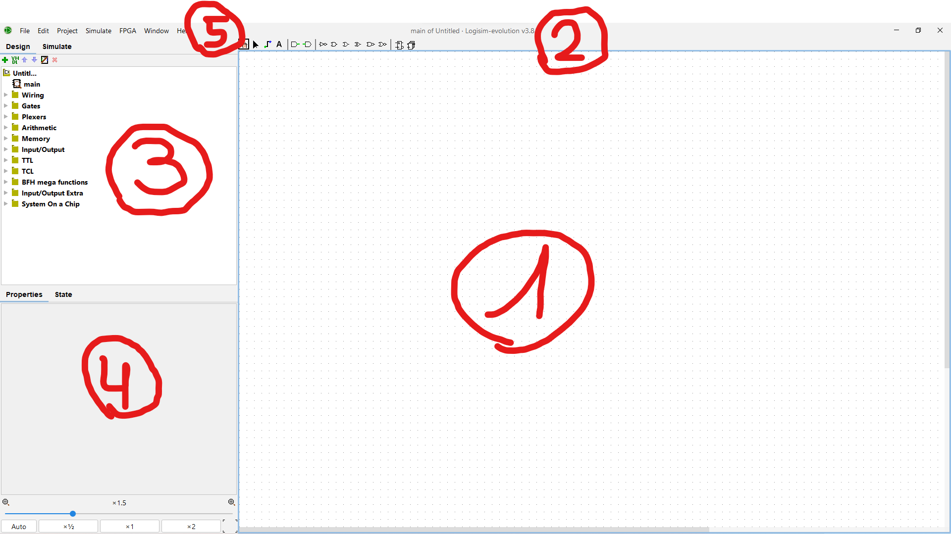
1. The working area
It is in this large space (empty for the moment) that the circuits are created by dragging and dropping components such as logic gates, wires, and so on.
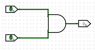
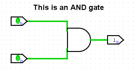
As an example, the work surface could contain elements like this (an AND gate with two inputs and one output) :
2. The toolbar
These tools are used to modify the circuit in the working area.

From left to right :
The hand
The hand can be used to modify the values of the circuit's inputs. Once this tool has been selected, it is possible to click on the inputs to change their value (the value changes from 0 to 1 or vice-versa).
Note that this process even works with multi-bit inputs. Simply click on each bit individually to change it.
The pointer
This tool (which looks like a mouse cursor) can be used to modify the circuit in the broadest sense of the term.
In particular, you can select elements of the circuit, move them and link them with wires.
TIP
To link elements with a wire, hold down the mouse click and drag the cursor to the second element.
The wires
Whereas the pointer tool can be used to add wires linking one element of the circuit to another, the wire tool can be used to add wires without necessarily starting from an element. The pointer tool is generally more widely used.
The text
Extremely organized people will be delighted to learn that Logisim allows you to leave comments on your circuit (so to speak). The text tool can be used to add blocks of text to the circuit.
Although this is clearly unnecessary in this instance, some people will find it helpful when projects become more complex.
IMPORTANT
Adding comments is not mandatory in the course, unless otherwise instructed by the teacher.
Inputs and outputs
The following two tools are used to add inputs and outputs to the circuit (green bars to the right and left respectively).
The green bar for an input points to the right to show that the current is 'entering' the circuit, and vice-versa for the output.
To add an input, select the corresponding tool, then click in the work area where you want to add an input. The same applies to outputs.
TIP
It is possible to create multi-bit inputs/outputs by manipulating their properties.
NOT, AND, OR, XOR, NAND, NOR, D-FLIP-FLOP, REGISTER
All the following tools are logic gates to be added to the circuit in the same way as an input/output (except for the D-Flip-Flop and the Register which are elements seen during the semester).
When in doubt, hover the mouse over a tool to see the name of the gate.
WARNING
Be careful to respect the TP criteria if there are any. In some sections, only certain logic gates will be authorised.
3. Additional components
The toolbar contains the main components, but there are many others.
Some of the following tutorials are dedicated to specific components. These can be found in the hierarchy at the top left :
A hierarchy of folders can be found under logisim_interface (which is the title of the project). These folders group together by category less frequently used components, some of which will still be useful for DSD.
TO BE CONTINUED
Additional components are a vast subject. Some of the next tutorials are dedicated to the Splitter, the Clock, the DIP-Switch and the 7-Segment Display. These are components used during the semester which will probably be introduced in the practical exercises.
It is also possible to create sub-circuits that can be used as components in other circuits. This will be the subject of another tutorial.
4. Properties
By selecting a circuit element with the pointer tool, its properties will be displayed in this tab. You can then adjust them as required :
The properties will be the subject of a separate tutorial.
5. The menu
Like many applications, Logisim has a menu at the top right which allows you to :
- Save the current project
- Open an existing project
- Manage the circuit simulation (see tutorial on clock)
- Test your circuit on a GECKO (FPGA)
- Generate a circuit automatically from a truth table (see the tutorial on this subject)
The parameters can be found in File > Preferences.
Appendix
The Logisim project used for the screenshots in this tutorial can be download via this link.