Generate circuits (Logisim)
In some cases, it takes a long time to create circuits by hand, but it's easier to generate them automatically.
Logisim is capable of automatically generating circuits from truth tables.
Example of use
Let's take the example from the previous tutorial where we wanted to create a bit adder.
The circuit has three inputs A, B and carry, and two outputs, result and remainder.
The circuit is perfectly feasible by hand, but in this case it is more interesting to generate it automatically by giving Logisim its truth table.
Combinatorial analysis
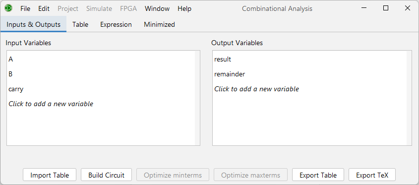
In the menu, Window > Combinatorial Analysis should open a window like the following :
List variables
In the first tab, Inputs and Outputs, we list the input and output variables, like the truth tables discussed in DSD class.
For our example circuit, we have A, B, carry as inputs and result, remainder as outputs, like this :
Completing the truth table
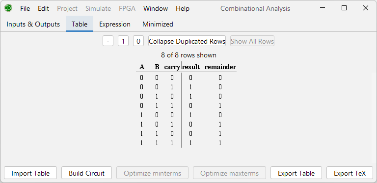
The next tab, Table, allows you to give the desired results for each combination of input variables.
For example, if A and B are both 1 but carry is 0, then we will have a 0 for result and a 1 for remainder.
Every line in the table must be filled in this way. A - means don't care, i.e. Logisim will freely choose the value depending on what simplifies the circuit.
The table for our example circuit looks like this :
Expression and Karnaugh diagram
Once the table has been completed, Logisim generates the logical expression corresponding to the truth table given in the Expression tab.
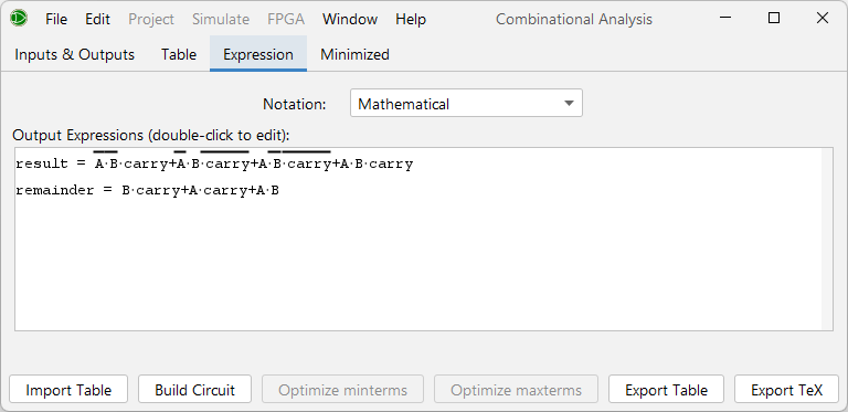
Logisim also generates the Karnaugh diagram corresponding to the expression and finds a minized expression to describe it, in the Minimized tab.
Generate the circuit
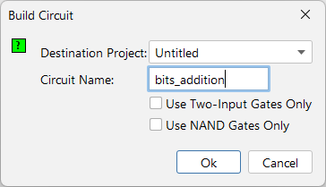
Once all this data has been obtained, Logisim is able to generate the circuit. It can be instructed to do this via the Build circuit button at the bottom left of the combinatorial analysis window.
Certain properties of the circuit can be modified, such as the destination project or the circuit name.
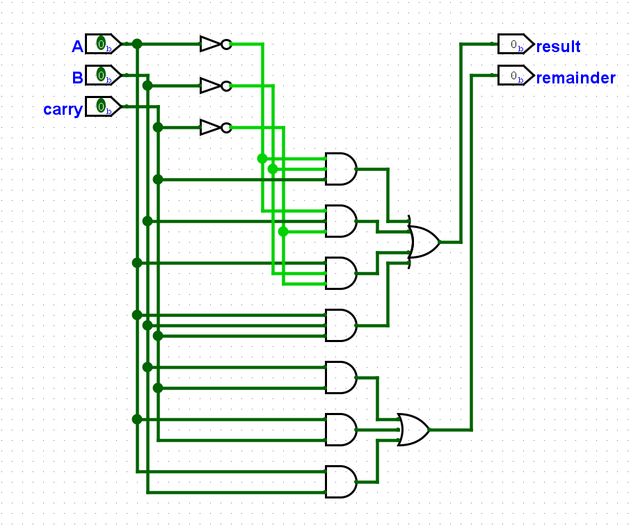
As an example, here is the circuit generated without any particular constraints :
Other possibilities - importing and exporting truth tables
You can import a truth table in the form of a text file containing the required values.
It is also possible to export the truth table once it has been created and filled in.
The truth table used in this example can be downloaded from the appendix.
Appendix
The Logisim project used for the screenshots in this tutorial can be downloaded from this link.
The truth table used can be downloaded via this link.